What 8N1 looks like on the wire
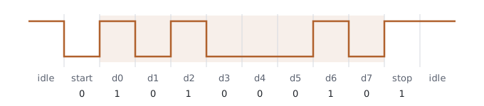
One UART byte, bit by bit: idle, start, eight data bits LSB first, stop.
Every UART config screen says “8N1”, and most of us set it and move on. Here is what it means when you put a logic analyzer on the TX pin.
The frame#
The line idles high. A byte goes out as ten bit-times:
- Start bit: the line drops low for one bit-time. This falling edge is what the receiver syncs on.
- Eight data bits, least significant bit first.
- No parity (the “N”).
- One stop bit: the line goes high again (the “1”).
Here is 'E' (0x45, binary 0100 0101) leaving the pin. Read LSB first,
the data bits come out as 1 0 1 0 0 0 1 0:
Timing#
One bit-time is 1 / baud. A frame is ten bit-times, so the useful byte rate
is the baud rate divided by ten1:
| Baud | Bit time | Frame (10 bits) | Max bytes/s |
|---|---|---|---|
| 9600 | 104.17 µs | 1.042 ms | 960 |
| 115200 | 8.68 µs | 86.8 µs | 11 520 |
Sending it by hand#
A bit-banged transmitter makes the frame obvious. This is a sketch for illustration, not production code: real firmware uses the UART peripheral, and a busy-wait delay is only accurate enough at low baud rates.
#define BIT_US  104u   /* 9600 baud: 1 / 9600 s is about 104.17 us */

static void uart_tx_byte(uint8_t b)
{
    gpio_write(TX_PIN, 0);              /* start bit */
    delay_us(BIT_US);

    for (int i = 0; i < 8; i++) {       /* data bits, LSB first */
        gpio_write(TX_PIN, (b >> i) & 1u);
        delay_us(BIT_US);
    }

    gpio_write(TX_PIN, 1);              /* stop bit; line stays high = idle */
    delay_us(BIT_US);
}
The receiver does the mirror image: wait for the falling edge, move to the middle of the start bit, then sample once per bit-time.
This ignores any idle time between frames. Back-to-back frames hit this ceiling; real traffic usually has gaps. ↩